
Einleitung
Diese Nachttischlampe ist ein bisschen schwierig zu öffnen, aber mit dem richtigen Werkzeug gelingt es. Ein Werkzeug mit einer stumpfen dünnen klinge, z.B. iFixits Jimmy erleichtert das Öffnen sehr.
Die Anleitung gilt für einige ähnliche Modelle: HF3520, HF3560, HF3531, HF3501 und HF3510.
Zweck hierfür war einen Antennenanschluss (BNC) zu installieren um eine Teleskopantenne oder Dachantenne anzuschließen. Die Anleitung ist aber auch nützlich für Reparaturen an der Hauptplatine.
Werkzeuge
-
-
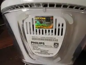
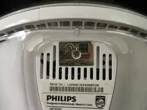
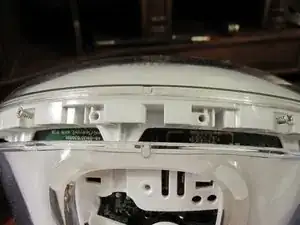
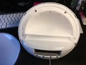
Unter dem glänzenden UL-Aufkleber befindet sich eine Schraube. Entferne den Aufkleber oder schneide ihn ein und entferne die Schraube, um diese Bodenplatte abzulösen.
-
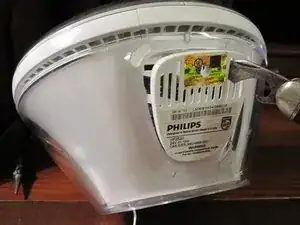
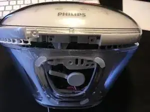
Es gibt zwei Laschen, die das Panel auf der Rückseite der Uhr/des Lichts halten. Wenn es nicht leicht abgeht, musst du mit einem Spudger oder einem Flachschraubendreher am Panel nahe bei der Schraube nach vorne und außen wackeln.
-
-
-
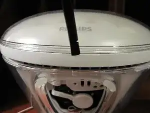
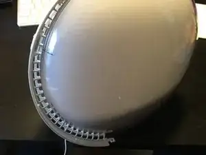
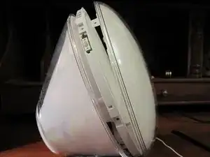
Lege die lamtauf Rückseite, dann wird ein kleiner Abschnitt der Blende sichtbar, der nach oben gehebelt werden kann. Es ist ein kleiner Plastikstreifen mit Haken, die gelöst werden müssen, um sie zu entfernen.
-
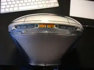
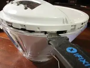
Schiebe die Klinge eines Jimmys direkt in die Spalte über der Abdeckung. Wenn sie sich einige Millimeter geöffnet hat, kippe sie und hebe sie leicht an.
-
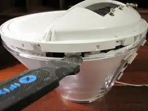
Schiebe den Jimmy nach rechts und drücke ihn gegen den Riegel, bis er sich löst. Wiederhole auf der linken Seite.
-
-
-
Wir können endlich zwei weitere Kreuzschlitzschrauben lösen, um den Knopfring zu entfernen.
-
Tipp: Hebe den Ring an einem Ende hoch, wobei du ihn zur Rückseite des Weckers hin kippst. Dadurch lösen sich die Haken unter der rückseitigen Rille und du kannst ihn weiter ablösen.
-
-
-
Nun müssen die sechs Schrauben entfernt werden, die die vordere Abdeckung festhalten. Dann kann die vordere Abdeckung nach vorne abgezogen werden.
-
-
-
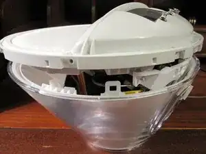
Die innere Lichteinheit wird von zwei Laschen unten links und an der rechten Seite gehalten.
-
Nimm ein Metallwerkzeug mit dünner stumpfer Klinge, z.B. einen Jimmy und drücke die hintere Lasche nach innen, bis sie sich löst.
-
-
-
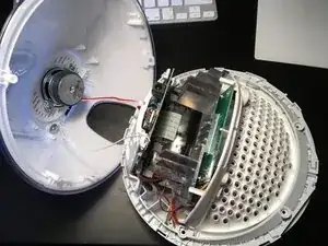
Trenne den Lautsprecher von der Hauptplatine ab.
-
Löse die Schraube und die Unterlegscheibe auf der Rückseite beim Lautsprecher und hole den Antennendraht darunter heraus. Ziehe die Antenne ganz durch, so dass die Rückseite entfernt werden kann.
-


14 Kommentare
Awesome teardown except for one little thing…
The factory sticker shows this is a 3530 which may not be different from a 3520. However, the bottom plate screw MUST be removed in order to separate the two halves. It is a little confusing saying “The bottom panel does not help gaining access to more screws. See next step.” I took that as being unnecessary, so skip.
I was able to fix my speaker inside it i got this alarm at a thrift store for cheap turns out the one wire just needed a better conenction to get working thank you for the steps to get to it
The first photo of step 5 is a little misleading, it looks like you are unscrewing something, it made me look for the screws
Other than that this was very helpful, thank you
There is one screw under this tab that's hold the front ring attached in fact. I guess you should have removed it too before prying this ring open
Luuk Akkerman -
That one does not hold the ring but the cover (step 4).
Wozu das denn -